Flue Gas Desulfurization
EKATO in FGD Plants since 1979
Since 1979, when the FGD market rose in Europe and the USA due to more stringent emission limits, EKATO equips coal fired power plants with agitators specifically designed for the extreme demands on the equipment and set the benchmark for todays used technology. With more than 12,000 agitators sold worldwide, EKATO is the No.1 agitator supplier in this market.
During the first years of the 1980s, the absorber sump of an FGD plant was generally equipped with a sparger grid to inject the oxidation air into the process. The little outlets of the pipes were easily plugged by the solids and led to significant investment, repair and maintenance costs.
Under this aspect EKATO developed in 1983, with numerous from lab tests to operational scale, the agitator gassing system with the oxidation-air-lance placed in front of the impeller. With this new development EKATO set the first benchmark on the FGD market. Nowadays more than 90 % of all modern FGD plants worldwide are using this kind of agitator-lance-system. One other big issue in the FGD process is the high abrasion on the impeller blades forced by high solid concentration and flue ash. Extending the life-time, was the goal for developing the EKATO Wingjet impeller.
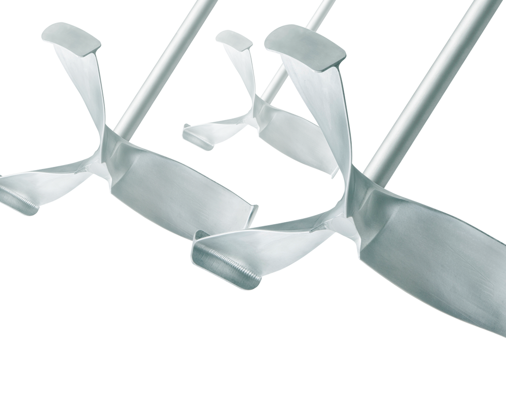
In 1994, EKATO discovered the innovative approach in the aircraft construction. At the wingtips of modern jets, you will find a so called winglet. Inspired by that, the EKATO Wingjet has a winglet at each blade which highly reduces the vortex created by the pressure compensation at the blade tips, the main reason for abrasion. This impeller design still remains the benchmark for today’s FGD Agitators.
Process
There are three main desulfurization processes, each of which is applied in a number of modifications:
- dry (additive absorption or adsorption)
- semi-dry (absorption)
- wet (lime or ammonia absorption)
Because the absorbents lime and ammonia are readily available and the product of the wet process is easily used or disposed of, this process is now employed by over 90% of all desulfurization plants worldwide. The picture provides a simplified flowchart of such a plant, in this case the two-stage KRC flue gas desulfurization process. With this process, the sulfur dioxide (SO2) contained in the flue gas is absorbed chemically in an aqueous washing suspension of limestone (CaCO3), quicklime (CaO), or slaked lime (Ca(OH)2) according to the simplified formula
SO2 + CaCO3 → CaSO3 + CO2
and then oxidized with atmospheric oxygen O2 in a series of steps to produce gypsum (CaSO4):
CaSO3 + O2 → CaSO4
If limestone is used, one starts the process by mixing limestone flour and water in a preparation tank and then transferring the resulting suspension to the scrubber feed tank. Because the absorption process reacts sensitively even to tiny fluctuations in the scrubber feed, the particle distribution in the limestone suspension has to be absolutely uniform – despite widely varying tank geometries.
The cleaned gas leaving the plant is used to cool the incoming flue gas down to about 50°C. The latter is then fed into the side of the one- or two-step scrubber. Mounted above the flue gas inlet are a number of levels of nozzles, which spray the gas with continuously recirculated washing suspension. Using the counterflow principle, this effectively washes the SO2 out of the flue gas together with other acidic and toxic gases (hydrochloric-acid gas, hydrogen fluoride).
The suspension then runs down into the absorbent sump below the flue gas inlet. Here the intermediate products that have formed (calcium sulfite, hydrogen sulfite) are oxidized by air blown in through lances to produce gypsum. The resulting gypsum suspension is passed via hydro cyclones (for separation and recycling of fines) into the gypsum suspension tank. After being dewatered and dried, the gypsum is available for various uses, e.g. in the construction industry.
Besides the flue gas treatment just described, which prevents air pollution, extensive measures are also required to treat the process’s wastewater.
Agitation Technology
Suspending
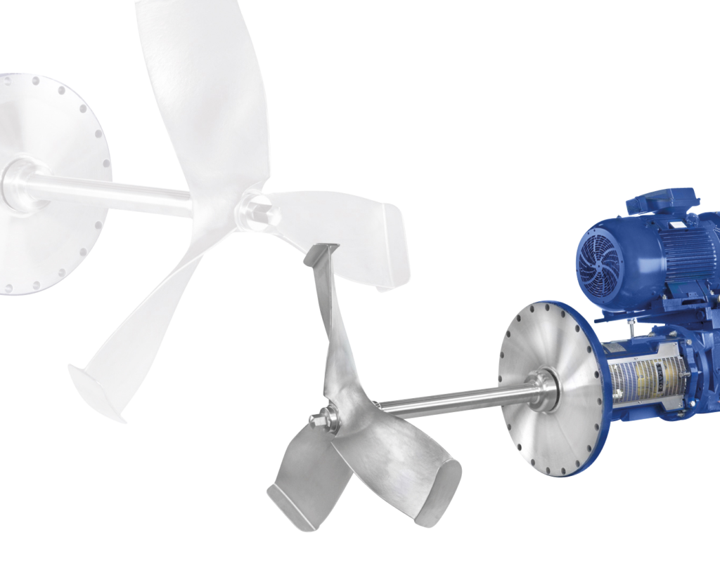
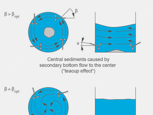
The horizontally mounted agitators installed in a number around the scrubber tower will maintain a complete and reliable off-bottom suspending. Any sedimentations and buildup of the in the scrubber sump formed gypsum particles have to be avoided for an uninterrupted continuous operation of the scrubber tower.
This is achieved by optimal angular settings, both vertically (α) and laterally (β), plus strategic placement of the agitators around the scrubber.
Without the correct angle adjustment and too much distance between the agitators, sediments can occur in the center of the vessel or on the vessel wall which can lead to plugging of the pump nozzles. The ideal angle adjustment depends on the scale.
Gassing system
If the calcium sulfite is produced from the sulfur dioxide and lime is oxidized to gypsum with air from crossed-pipe gassing systems (fix sparge grid), the scrubber agitators have to keep the solids in suspension in the scrubber sump.
But such crossed-pipe gassing systems are material-intensive and inflexible in partial-load operations. They are also highly susceptible for clogging what is leading to a reduced oxygen mass transfer.
The by EKATO developed agitator-lance gassing system represents a substantial simplification compared with crossed-pipe gassing. This system employs one or more lances on the pressure side of the impeller to introduce the oxidation air. Here it is dispersed in fine bubbles by the high flow velocities of the by the impeller created flowing stream and distributed over the vessel’s cross section.
This agitator-lance gassing system became soon the standard in the wet limestone FGD process as it offers great advantages.
Advantages of the EKATO Agitator-Lance gassing system:
- Highly efficient oxygen mass transfer, which reduces the amount of oxidation air required by up to 30% compared to sparge grid gassing systems.
- The fine bubbles which are produced by the high flow velocities applied by the impeller, have an extremely large aggregate surface area, which creates a much more efficient oxygen mass transfer than a bubble column with large bubbles.
- Long bubble residence time
- Most of the sparge grid gassing systems introduce the air at a level above the agitators. The lances of the EKATO agitator-lance gassing system however distribute the oxidation air at the much lower agitator level. Better coverage and smaller bubbles prolong residence time, thus enhancing oxygen utilization.
- Minimum installation costs due to reduction of the amount of piping in the vessel
- No risk of clogging
The large pipe openings are very unlikely to clog up. As a result stable efficiency of the oxidation air dispersion in continuous operation as well as lower maintenance costs are provided.
Agiator Design
EKATO agitators are designed and manufactured for fatigue live based on rated motor power and maximum applying dynamic loads. For the design infinitive cycles of the dynamic loads are considered. EKATO agitators are proven reliable and long term in operation even under severe process conditions like in a FGD service.
EKATO WINGJET
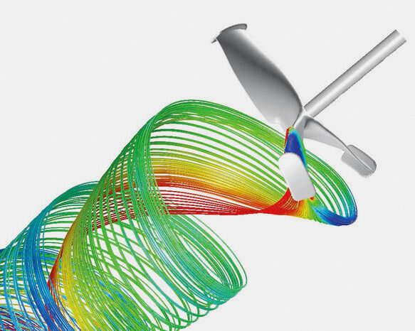
The EKATO Wingjet, an impeller specifically developed for the use in FGD absorbers. With its CFD optimized geometry and its cast formed blades this impeller offers the following advantages:
- Maximized efficiency
- Bundled axial flow
- Increased pumping capacity
- Winglets suppressing the tip vortex for reduced impact corrosion, longer operational life and reduced maintenance costs.
The EKATO Wingjet impeller is constructed of highly corrosive and abrasive resistant Super Duplex materials. Available in diameters: 800…2000mm
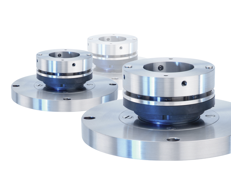
Mechanical seal ESD 42L
Single acting product lubricated mechanical seal for the FGD side entry agitators. This cartridge type mechanical seal is specifically designed for highly abrasive and corrosive medium providing long lifetime and easy maintenance on-site.
Shut-off Device
The shut-off device makes it possible to service the mechanical seal, or even replace it entirely, without shutting down or emptying the absorber tower.
Materials
Properly selected materials considering the pH level, the temperature and the chlorides, fluorides, solids and oxygen in the media being agitated are essential for reliable agitators with long lasting lifetime.
In practice there are two fundamental cases:
- Use of alloy metallic materials for the side mounted absorber agitators
- Use of unalloyed carbon steel lined with hard or soft rubber for the vertical top mounted agitators
The parts of the side entry agitators coming into contact with the highly corrosive and abrasive media are made of Super Austenitic stainless steels or made of Super Duplex materials.
The EKATO Wingjet impeller is made of a cast formed Super Duplex material. In addition a gapless design and sealed connections of the parts in contact with the product minimizes crevice corrosion and pitting by the acidic media and their chlorides
References
EKATO FGD agitators are installed and successfully in operation in hundreds of power plants worldwide since 1980. With more than 12,000 agitators sold worldwide to over 1,500 FGD plants, EKATO is the No.1 agitator supplier in this market. For a detailed reference list worldwide or for a specific region please contact us.

EKATO Side Entry Agitatorsfor FGD absorbers


